Api Oil Water Separator Calculation

Api Oil Water Separator Simplified Sketch Download Scientific Diagram

Api Separator

Api Series Oil Water Separators
Oil Water Separator Blog Api Oil Water Separators

Novel Design Methods For Conventional Oil Water Separators Sciencedirect
Fact Sheet Oil Water Separators
10 15 2001 8 55 40 pm company.
Api oil water separator calculation.
Https Www Oilandwaterseparator Com Wp Content Uploads 2014 12 Stormwater Processing Separator Design 2014 Pdf
Https Www Mcgill Ca Bioeng Files Bioeng Hsin Hui Sebastien Yue 2011 Pdf
Api Separator Sizing Cheresources Com Community

Oil Water Separator Api Sizing Instruction Pump Water
Above Ground Oil Water Separator Specifications And Drawings Wash Bay Solutions International Advanced Oil Water Separators
Http Www Deq Idaho Gov Media 618110 18 Pdf

Api Oil Separators Chemical Engineering Water
Https Www Epa Gov Sites Production Files 2014 04 Documents 5 Owseparators 2014 Pdf

Oil Water Separators Wash Bay Solutions International Advanced Oil Water Separators

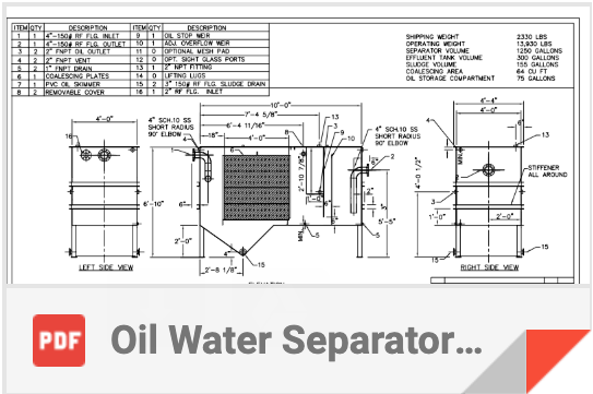
Oil Water Separator General Arrangement Drawings

Maxisep Oil Water Separator
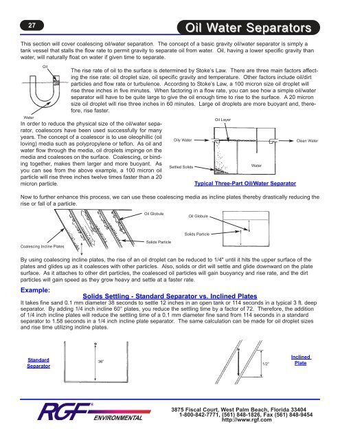
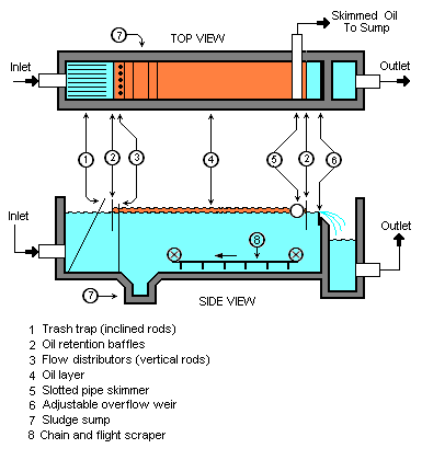
Oil Water Separators

Design And Sizing Of An Oil Water Separator

Oil Water Separator Api Sizing Instruction Pon2x2z85ml0
Source : pinterest.com
